PupperPy
Codename: CERBARIS
Our build and extension of the Stanford Pupper Robot. Codename: C.E.R.B.A.R.I.S.
Project maintained by campusrover Hosted on GitHub Pages — Theme by mattgraham
Introduction | Team | Hardware | Software Overview | Software Setup | Computer Vision | Collision Avoidance | Web Interface | Odometry | Behavioral Control |
Build/Assembly
The robotics kits was dontated by the Hands-On Robotics Initiative. It came with the full set of parts and all of the tools needed to build robot. Assembly was fairly straightforward and generally followed the official Pupper build guide except as noted below. Our inital build took roughly 10 hours, though later, an almost complete teardown and rebuild took less than 4 hours. A huge part of this change in assembly time was simply having a second hex screwdriver that fit the M3 button head screws.
Build Notes and Deviations from the guide
- When setting the servos to their neutral position, keep in mind that the servos rotate slightly over 180 deg. As such it is difficult to set them to exactly neutral. Regardless, what is most important is to come up with a method for determining neutral and then being consistent on all motors.
- When attaching the metal disks to the servos, use the M3x6 socket head screws.
- When attaching the carbon fiber leg pieces to the servos, use the M3x6 button head screws.
- To attach the upper leg extension (the silver threaded rod / hamstring), use the M3x10 button head screws and the locknuts on both the upper and lower connections (not just the lower).
- For body assembly step 3, there are no M4x8 plastic screws, instead use the M4x10 screws
- For body assembly step 4, it says to use M3x6 screws, but instead use M3x8
- To attach the top and bottom plates, use M3x8 screws instead of M3x6
- The 3D printed plate with the tiny slit cutout is the back of the robot, the solid plate is the front of the robot.
- When mounting the legs onto the middle 3D pritned body parts, be very careful about orientation. If those plates are mounted backwards then the screw holes will not line up with the top and bottom plates.
- Several times during operation, the hamstrings would pop out. That is the threaded rod would detach from the black end-pieces. During assembly, screw those end-pieces on as tight as possible. I would even recommend using some loclite or super glue on the threads to really hold them in place.
Battery & Charging
The pupper came with a 5200mAh 2S LiPo Battery. To properly charge the battery we used the LiPo battery charger in LiPo Balance Charge mode with 5.2A current and 7.4V(2S). On the machine, simply plugin the yellow and white connectors on the battery and scroll to the LiPo balance charge setting and press play. It should auto-detect the appopriate settings and simply ask you to confirm. You can use the +/- button to change the setting and hold play to confirm. It will then ask you to confirm the 2S charge rate and then it will charge.
From fully depleted the battery was able to charge in about 45 minutes. A full charge can power the robot and all peripherals for roughly 1.5-2hrs.
Repairs
First damage
Once while calibrating the right front leg ran into and got stuck on a usb cable plugged into the pupper. Since the leg continued to try and go to the position it was told to, extreme strain was placed on the green metal spacers connecting the inner and outer hip casings. These 3D pritned parts cracked and we had to get new ones and swap them out.
Next damage
After this was repaired we let the pupper run autonomously for ~45min. During this time we noticed the pupper getting lower and lower to the ground over time, especially in the front. When we stopped operation we noticed that cracks had appeared around the same screw holes but now on 3 separate hips. On this occasion the robot never crashed or collapsed and there was nothing obstructing leg movement. Our best guess is that during operation, the button head screws between the inner and outer leg motors loosened and began to hit each other. Also brittleness or weakness of the PLA 3D printed parts may simply be unable to handle to movement of the robot for exteded periods of time.
We repalced all of the hips with nylon 3D pritned parts with slightly thicker walls, and now the robot is very stable. The new parts seem both more durable and more flexible than the previous parts.
Sensors
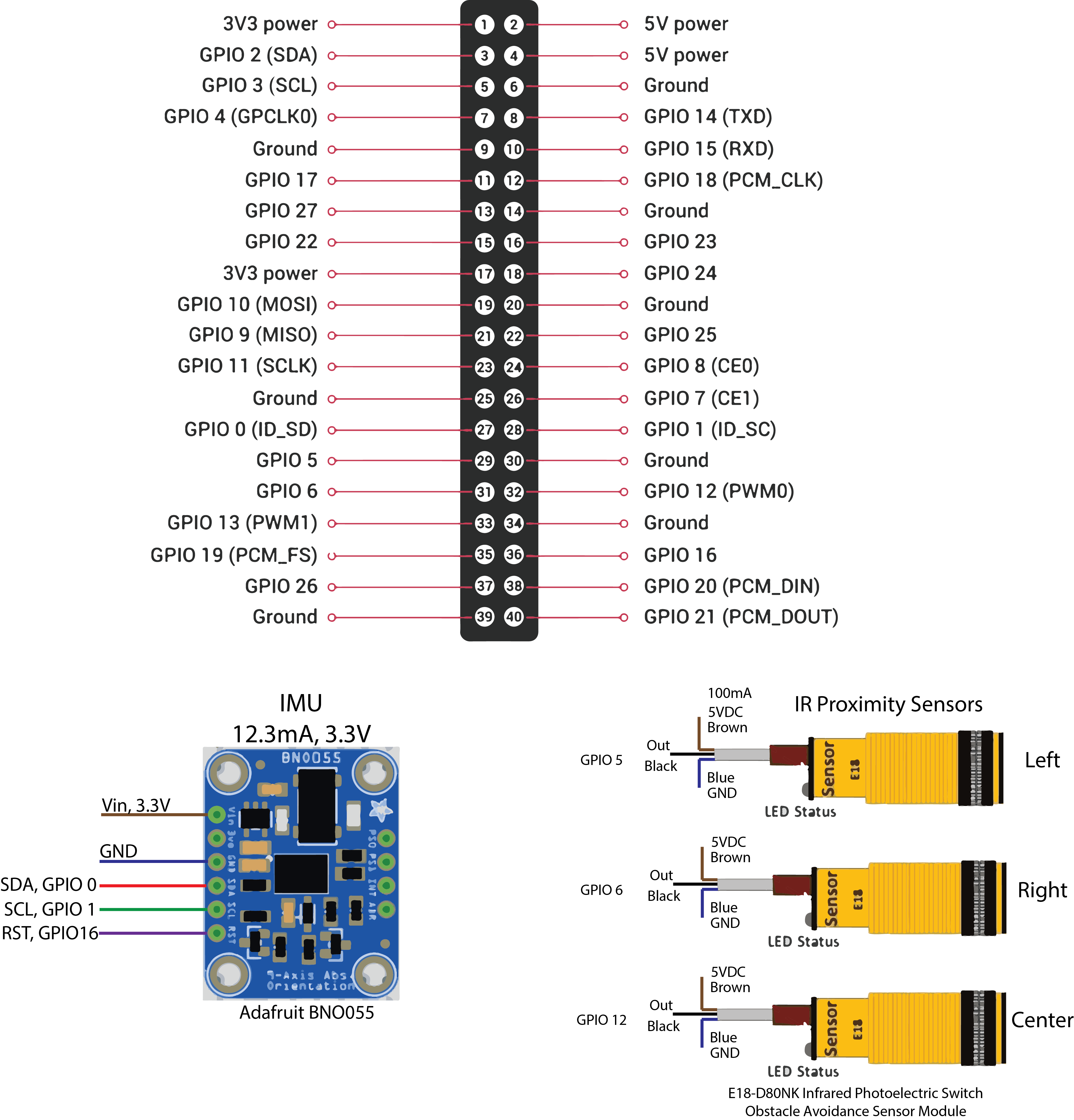
Here is the a connection diagram for attaching the IMU and object sensors to the raspberry pi.
Intertial Measurement Unit (IMU)
We chose to install a 9-DOF IMU in hopes of accurately tracking orientation and position. To this end we used the Adafruit BNO055 Absolute Orientation Sensor which boasts on-board sensor fusion. This means that this unit already takes sensor readings from the gyroscope, accelerometers and magnetometer and appropriately rotates the data to provide euler angles relative to magnetic north and linear acceleration values with gravity already removed.
While some tutorials online suggest connecting the BNO055 to a Raspberry Pi in UART mode, this is outdated and does not work. Instead you have to connect it with the default I2C protocol. However, the primary I2C headers on the Pi 4 are in use to control the pupper’s motor. As such we connected the IMU I2C connection to GPIOs 0 & 1 (Pins 27 & 28) and then used a device-tree overlay to enable a software I2C bus on the raspberry pi. Details on how to do this are in the software setup section. Though some information on setting up the IMU can be found here as well.
An important note is that the IMU Vin must be connected to 3.3V power and not 5V, even though the specs say that it should be able to operate with 5V power. The one time we attempted to use 5V power with the IMU, the pupper refused to boot up at all.
IR Object Avoidance Sensors
For our setup we chose to use 3 digital IR object avoidance sensors in order to detect the presence of obstacles and avoid collisions while moving. To this end we bought 3x E18-D80NK Photoelectric Switch Obstacle Avoidance Sensor Modules from Amazon, and mounted them onto the pupper with a custom designed and printed sensor mount.
These sensors are setup to look forward and 25 degrees to each side, and can detect objects up to 30cm away. A small screw on the back can be tuned to set the detection range. At default, with no object, the sensors send a HIGH signal to the raspberry pi and switched to LOW when an object is detected. The sensors require 5V power input and the outputs were connected to GPIOs 5, 6 & 12.
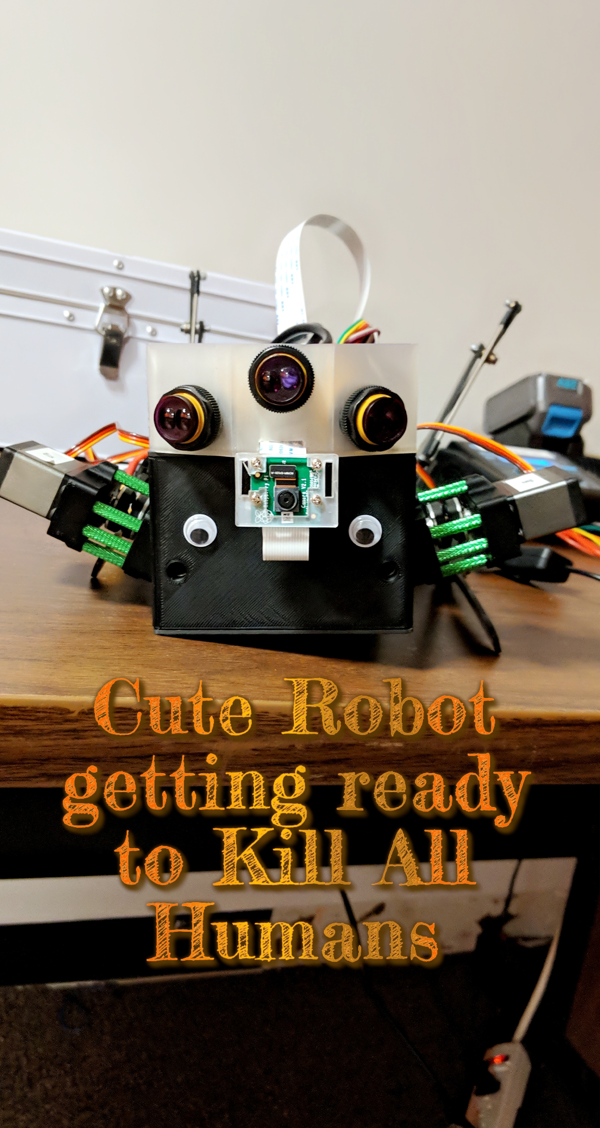
Camera
We also attached a standard raspbery pi camera with an acrylic case that was attached to sensor mount with a velcro strip.