PupperPy
Codename: CERBARIS
Our build and extension of the Stanford Pupper Robot. Codename: C.E.R.B.A.R.I.S.
Project maintained by campusrover Hosted on GitHub Pages — Theme by mattgraham
Introduction | Team | Hardware | Software Overview | Software Setup | Computer Vision | Collision Avoidance | Web Interface | Odometry | Behavioral Control |
Odometry using a 9-DOF IMU
IMU
For tracking of movement, we used the Adafruit BNO055 Absolute Orientation Sensor. This module provides quite a lot of information about movement and orientation in several different forms. For the purposes of the current project we used the sensor fused outputs of linear acceleration and euler angles in order to update a Kalman filter which kept track of x & y position relative to the starting point in cartesian space, x & y velocity and acceleration relative to the robot’s heading (with the robot’s forward direction being the +x direction), the robot’s heading (yaw) and yaw rate.
Hardware interface
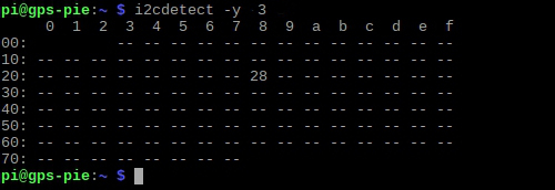
As mentioned in the hardware section, the BNO055 communicates with the raspberry pi through an I2C connection. In the current configuration, the IMU is at address 0x28 on i2c bus 3. You can check that the imu is properly connected using the i2cdetect tool.
sudo i2cdetect -y 3
The output should look like this if the imu is properly connected:
Python communication with the IMU is handled through the Adafruit CircuitPython BNO055 library with some caveats. Since the motors are using the hardware I2C ports on the Pi we had to setup a software I2C bus on GPIO 0 (SDA) & 1 (SCL); however, circuitpython is not designed to work with software I2C busses. For this reason we created our own extension of the busio.I2C class. The simplest method of interfacing with the IMU is to simply instantiate our pupperpy.imu_tools.IMU object, which will connect to and read from the IMU.
from pupperpy.imu_tools import IMU

imu = IMU()
imu.sensor # this will give you direct access to the imu sensor data from circuitpython

imu.read() # this will return a dict containing basic sensor fused data,
           # orientation, linear accelerations and calibration status of sensors

imu.log(time, rate) # this will log imu data for 'time' seconds at 'rate'
                    # samples per second
The imu.sensor is the direct link to the sensor, which is the BNO055_I2C class.
If an IMU object is closed/deleted, re-creation of the object immediately occassion gives some form of I/O error, but this is usually solved by simply waiting a few seconds and trying again.
Data quality and challenges
The orientation obtained from the IMU is the most accurate of the data gained from it, with yaw, pitch and roll being fairly accurate and not too noisy; though dropped packets – null readings – do happen from time to time. The acceleration readings are far less accurate.
The largest issues with the IMU data are noise and calibration. The BNO055 automatically calibrates while running, but resets calibration each time it powers up. Furthermore, each sensor requires different motions/orientations in order to fully calibrate. Due to complexity and time constraints were unable to implement a way to calibrate and store calibration values for the IMU which likely contributed a lot to the inaccuracy of our odometry.
For the next group attempting this, I recommend the first step be to calibrate the IMU sensors, read the calibration values from the registers directly and store them, and then write code to write those values back to the IMU on start up. Information for calibration and doing this process can be found on pages 47-48 on the Bosch BNO055 datasheet.
Kalman Filtering
A Kalman filter functions by maintaining a vector of all tracked values and using those values to estimate the values at the next time step. Then it uses the measured data to correct the estimated values, but scales the contributions of the observation and the estimation based on the relative error of the 2 processes. Additionally the Kalman filter tracks and updates the process covariance to help account for accumulated error. In this package the Kalman filter is designed to track:
- X position in cartesian space
- Y position in cartesian space
- X velocity relative to robot’s heading
- Y velocity relative to robot’s heading
- X acceleration relative to robot’s heading
- Y acceleration relative to robot’s heading
- Heading realtive to magnetic north
- Yaw rate – change in heading
The equations used for our Kalman Filter can be found in kalman.py in the repository.
Initially I tried to track all values on cartesian space but found that the
results were more accurate if the rotation from the egocentric to allocentric
space occurred at the position level and not the acceleration level.
The below figure shows the results of one test in which the robot walked along the green path and imu data was recorded at 10 Hz. THe yellow path shows the position decoding by simple integration of acceleration and the blue path is the kalman filtered data when the filter tracked all values in allocentric space. When we switched to only rotating the position information, the kalman filtered result matched the yellow path.
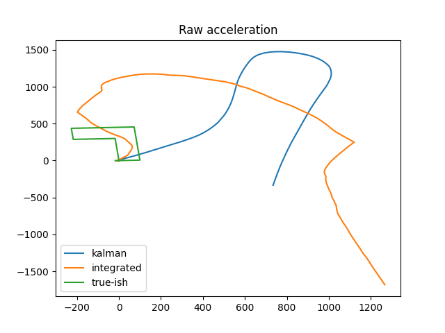
One key point in properly using a Kalman filter to decode IMU data is being able to add in some other source of information (either position or velocity) to help correct the decoding. In the attempt above this extra information was not present.
In the latest rendition, we have been attempting to augment the IMU data with the control velocity being sent to the robot, however this resulted in an extremely inaccurate position decoding during live operation. There are a few reason that live position decoding was inaccurate:
- We increased the sampling frequency for updating the Kalman filter to 100Hz
- The increased sampling rate resulted in much more noise in the imu data being sent to the filter
- The robot had a rightward drift in its movements
- This means that the control velocities did not match the actual velocities well
- I did not have time to properly tune the observation error and estimation error parameters
- These values are extremely important as they inform how the filter uses the measured data to update the prediction. Proper errors definitely must be chosen.
Moving Forward
At present the pupperpy.position.PositionTracker object is used to create and
update the KalmanFilter. This object has it’s own timer thread to query data at
~100Hz and update the filter. The PositionTracker also keeps logs of both
measurement data and output data. Moving forward a dataset with good ground truth data needs to be obtained so that the Kalman Filter can be fully tested offline. Due to time constraints we were unable to do this.
There are a few separate ways in which to improve the performance of the odometry:
- continue to collect data at 100Hz, but only update the Kalman filter at 10Hz feeding it an average of 10 measurements at each step.
- Calibrate the IMU, save the calibration values and write them to the imu registers on startup
- Add an ultrasonic range finder to get accurate X velocity with which to update the kalman filter
- Properly tune the observation and estimation error parameters.
- I basically guessed for most of these, so a lot of room for improvement here
- (Advanced) Convert the Kalman filter to an extended kalman filter
- This is rather difficult, and would involve re-deriving all of the equations using taylor series expansions of the non-linear functions and changing H to the Jacobian
Resources
These are some of the resrouces I used to get started with Kalman filter.